I have been trying to replicate the interior light functions of some of the newer cars for some time now. I like how they stay on after the door is closed and then fade away. This is also called theater lighting.
This circuit is based around the ever usefull 555 timer, and an N channel MOSFET.
I am building this for my 1969 Chevelle. Dakota Digital has something similar, but I didn’t want to spend $200 on it. I am working on replicating the retained accessory power too.

Here is the circuit on a prototyping breadboard.
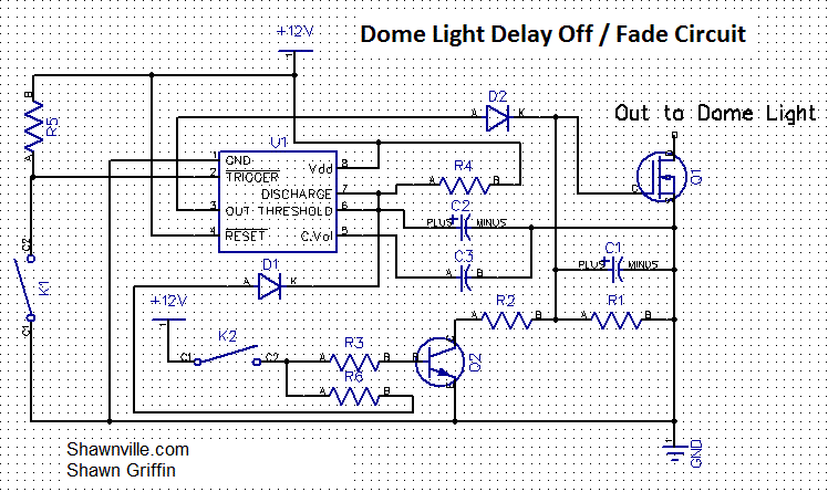
The capacitor (C2) & resistor (R4) connected to pins 6 & 7 on the 555 timer controls how long the output on pin 3 is high. A larger capacitor or more resistance will give you more time.
The fade effect comes from capacitor (C1) and resistor (R1), which pulls the voltage down slowly.
Dome Light Delay / Dimmer v3 Schematic

- K1: Switches on the doors connecting the trigger to ground.
- K2: Ignition switch to cancel the circuit — turn lights off immediately, unless doors are open.
- Q1: 2N7000 MOSFET
- Q2: NPN 2222 Transistor
- U1: 555 Timer
- C1: 22uF Capacitor
- C2: 100uF Capacitor
- C3: .02uF Ceramic Disc Capacitor
- R1: 447K Ohm 1/4 Watt Resistor
- R2: 1K Ohm 1/4 Watt Resistor
- R3: 1K Ohm 1/4 Watt Resistor
- R4: 10K Ohm 1/4 Watt Resistor
- R5: 1M Ohm 1/4 Watt Resistor
- R6: 1K Ohm 1/4 Watt Resistor
- D1: 1N914 Diode
- D2: 1N914 Diode


